
Key Takeaways
DC motor technology forms the backbone of modern automation, providing the mechanical torque required for everything from precise medical devices to industrial robots. This guide examines the fundamental operational physics and the practical distinctions between brushed and brushless designs.
- Electromagnetism dictates motor motion through armature and stator interactions.
- Commutation serves as the mechanism for switching current flow to sustain torque.
- Brushless motors replace physical contact with sensors and electronic control algorithms.
- Critical parameters like torque and speed constants determine application feasibility.
- Advanced control strategies utilize Pulse-Width Modulation for precise operational output.
Fundamentals of DC motor operation

Converting electrical energy to mechanical motion
At the most basic level, a DC Motor transforms electrical current into purposeful rotational work. This process relies on the relationship between electricity and magnetism, where current flowing through wire creates an electromagnetic field. When this field interacts with a permanent magnet, the resulting force generates rotation in the shaft.
The role of the armature and stator
Traditional design centers on two primary components: the armature, which rotates, and the stator, which provides the stationary magnetic field. Engineering this interface requires precise gap management. The Permanent Magnet DC design demonstrates how these components translate energy efficiently within small form factors, allowing developers to integrate compact drive systems directly into mobile robots or stationary machinery.
Understanding principles of commutation
Commutation is the process of reversing the direction of current within the armature coils to ensure continuous rotational motion. Without this reversal, the motor would stall as the magnetic poles align. By mechanically or electronically adjusting the current flow as the rotor passes fixed points, the magnetic repulsion force remains consistent throughout the full rotation.
Applying Fleming's left-hand rule to motor design
Engineers use Fleming's left-hand rule to predict the direction of force experienced by a current-carrying conductor in a magnetic field. By orienting the thumb, forefinger, and middle finger to correspond to force, field direction, and current, respectively, designers optimize winding layouts for peak performance. This proactive design verification ensures that motors achieve the required rotational orientation during prototype testing.
Brushed versus brushless DC motor designs
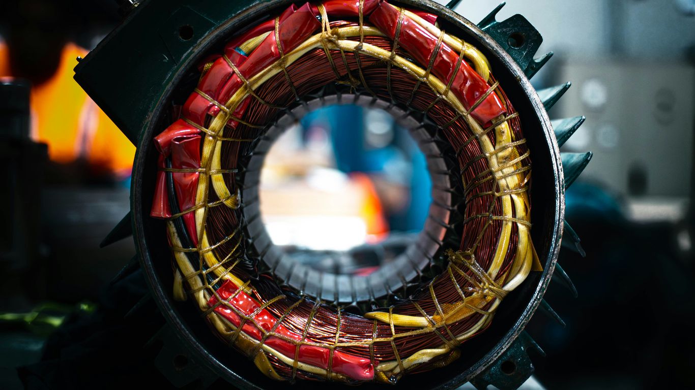
Mechanical commutation in brushed motors
Brushed motors achieve commutation through physical contact between carbon brushes and a split-ring commutator. This robust interface is well-understood, though friction and sparking are inevitable byproducts of the physical sliding action. While maxon brushed DC motors provide high reliability for specific industrial needs, the structural nature of the brush assembly necessitates periodic replacement to prevent signal degradation over time.
Electronic commutation in brushless systems
Brushless systems remove the physical brushes entirely, relying instead on electronic sensors and software to switch current paths. This eliminates physical wear, allowing for higher rotational speeds and potentially longer operational lifespans than their brushed counterparts. The transition to electronic control is essential in autonomous inspection platforms that require consistent reliability in hard-to-reach industrial settings.
Maintenance requirements and motor lifespan
| Motor Type | Maintenance Intensity | Typical Lifespan | Primary Wear Factor |
|---|---|---|---|
| Brushed | High | Moderate | Brush Erosion |
| Brushless | Low | Extended | Bearing Fatigue |
| Stepper | Low | High | Electronic Faults |
The table above highlights that choosing between brush types often involves trading off initial complexity for long-term maintenance requirements. Brushless architectures generally demand less physical oversight, benefiting applications where access is limited.
Performance differences in speed and torque
Brushless motors often demonstrate superior power-to-weight ratios due to the absence of heavy mechanical assemblies. They provide more consistent torque-to-speed curves, which simplifies the integration of advanced motion control. Brushless tech is increasingly preferred when designers need to minimize inertia in high-speed, high-precision environments.
Key performance parameters for selection
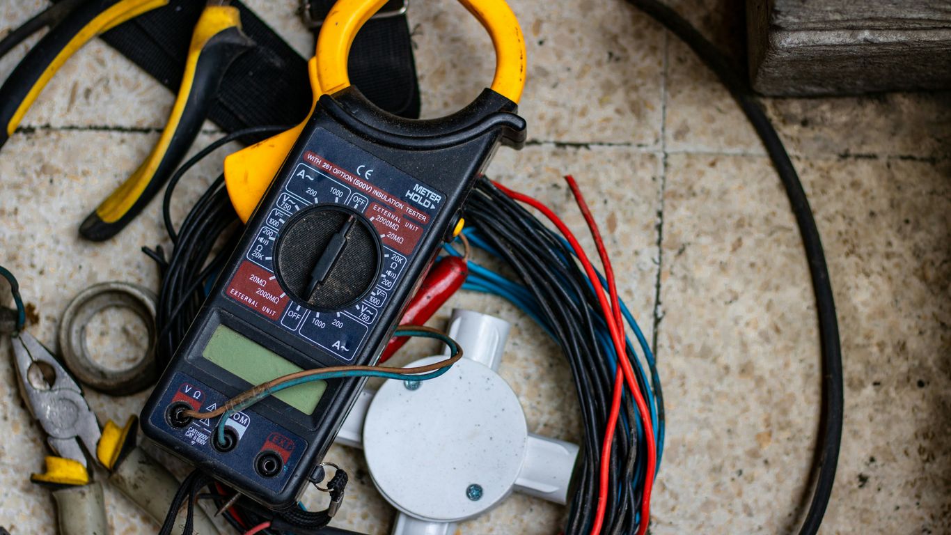
Calculating torque and power output
Torque effectively represents the rotational force a motor can maintain under load. Calculating this requires evaluating the relationship between terminal voltage, back-EMF, and armature resistance. Proper analysis prevents stalling and ensures that the motor remains within its designated thermal window throughout heavy operational duty cycles.
Understanding speed constant and voltage constant
Motor constants correlate voltage and output velocity. An increased speed constant indicates higher rpm for a given voltage, whereas the voltage constant defines how the motor behaves as a generator when rotated externally. These metrics allow engineers to forecast how the motor will react during acceleration and braking phases in real-world environments.
Efficiency ratings and thermal management
Thermal management is the practice of monitoring energy dissipation to avoid component failure. Even high-efficiency motors produce heat through internal resistance. Effective thermal cooling, whether through physical heatsinks or forced convection, is required to maintain the motor's performance envelope, especially in high-duty-cycle industrial environments.
Accounting for load inertia and duty cycles
Selecting the correct motor requires balancing various environmental and electrical variables to ensure stability. Engineers must consider several primary factors before final procurement:
- Peak torque requirements needed to overcome initial load inertia.
- Total duty cycle duration for heating and cooling balance.
- Electrical noise susceptibility in surrounding control circuitry.
- Mechanical compatibility with existing transmission shafts.
Monitoring these factors prevents premature hardware failure in sensitive robotic systems.
Applications and industry implementation
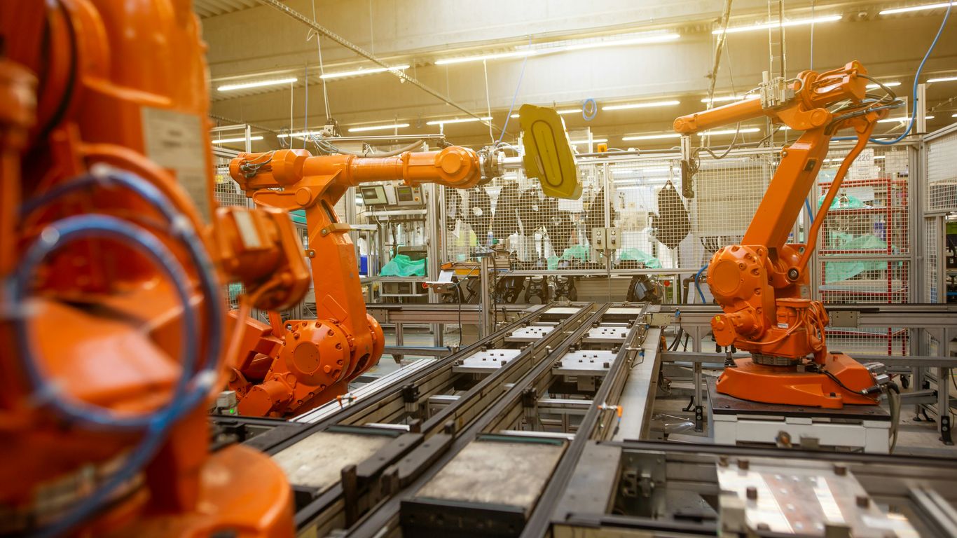
Small-scale systems in robotics and hobbyist devices
Small-scale DC motors power the rapid development within robotics, where compact energy density is vital. These devices often require rapid, precise start-stop capabilities to maintain stability during movement. The flexibility of low-voltage DC drive solutions remains critical for small, portable equipment.
Automotive and industrial propulsion systems
Propulsion systems in modern automotive designs mandate sophisticated motor architectures that support high current loads. These environments require significant torque consistency, often sourced from high-voltage DC windings that allow for adjustable speed, effectively replacing traditional gear-based mechanical transmissions.
Precision positioning in medical and aerospace equipment
Precision motors allow for the micro-adjustments critical to medical imaging and aerospace instrumentation. In these settings, the motor must operate without excessive vibration, requiring a blend of high-precision assembly and sophisticated electronic noise filtration. These systems prioritize accuracy over raw total power.
Integration into consumer electronics
Consumer electronics increasingly demand whisper-quiet operation and compact, integrated motor control. Whether inside small household automated tools or cooling systems, the push for miniaturization forces designers to move away from bulky brushed motors. This transition necessitates advanced PWM control schemes that minimize audible frequency output.
Control methods for DC motor speed and direction
Pulse-width modulation (PWM) basics
PWM is the industry standard for varying the effective voltage applied to a motor by rapidly switching it on and off. By controlling the duty cycle of these pulses, the system achieves precise speed modulation without the heat loss associated with traditional analog potentiometers. This method is pervasive in modern DC motor speed controllers used to manage dynamic power delivery.
Using H-bridge circuits for directional control
An H-bridge circuit acts as a gateway for current flow, allowing the motor to switch rotation direction by reorienting the polarity. By manipulating the arrangement of internal transistors, the bridge allows the control system to toggle between clockwise and counter-clockwise motion seamlessly. This is foundational for the development of autonomous systems where robots must navigate their environment and retreat from physical obstacles.
Closed-loop control with feedback sensors
Closed-loop systems integrate sensors like encoders or Hall-effect devices to monitor the rotor position. This feedback loop allows the controller to adjust duty cycles in real-time, compensating for sudden increases in external resistance or mechanical drag. Precision relies on this constant data flow between the motor and the central compute unit.
Variable voltage control techniques
Variable voltage strategies manipulate the raw signal amplitude to step speed up or down. While modern control leans toward pulse modulation, direct voltage modification provides a clean, continuous signal that may be preferred in environments where transient electrical noise must be avoided at all costs.
Maintenance and common troubleshooting
Visual inspection for carbon brush wear
Regular checks on carbon brush length are necessary to ensure consistent contact with the commutator. Once a brush wears past its threshold, surface pitting occurs, leading to intermittent power delivery and potential thermal spikes. Establishing a defined inspection interval prevents these issues from escalating into failure.
Identifying winding shorts and signs of overheating
Discoloration and localized burning within the armature windings indicate an electrical short or persistent overload condition. Engineers often utilize specialized testers to check for insulation breakdown before minor issues damage the commutator surface. Identifying these early warning signs of thermal fatigue is key to long-term reliability.
Testing bearing integrity and mechanical alignment
Bearings are the most common mechanical point of failure, often signaling their degradation through heat buildup or inconsistent drag. Checking for play and resistance during off-power manual rotation reveals misalignment or grease contamination. Keeping the shaft properly aligned preserves the lifetime of the motor bearings and maintains operational precision.
Interpreting unusual vibration or noise patterns
Audible or physical vibrations often indicate harmonic imbalances or loose mounting fixtures within the chassis. Using diagnostic equipment to capture these signals allows for the classification of vibrations, which helps determine if the root cause is mechanical in nature or a result of improper electronic switching cycles.
Conclusion
Mastering DC motor technology requires balancing physical mechanical requirements with sophisticated electronic control strategies. As efficiency and power density continue to improve, the role of these motors in autonomous and industrial systems remains pivotal. By carefully choosing between brushed and brushless architectures and optimizing control loops, engineers can build robust, reliable systems that form the foundation of next-generation infrastructure.
Frequently Asked Questions
How do I choose between brushed and brushless DC motors?
The choice depends on your requirements for lifespan and maintenance access. Brushless motors offer better performance for continuous-duty high-speed applications, while brushed motors may be more cost-effective for simpler, intermittent tasks.
Why does current reversal matter in a DC motor?
Current reversal, known as commutation, ensures that the magnetic forces on the armature continue to push in a consistent rotational direction. Without this, the motor would lock in place once the magnetic poles align.
What are the main indicators of motor overheating?
Warning signs include discolored wire insulation, an acrid smell of burning electronic components, and consistently high operating temperatures that exceed the manufacturer's thermal thresholds.
Is pulse-width modulation necessary for speed control?
While not strictly required, PWM is the most efficient method for controlling speed because it allows for granular adjustment with minimal energy loss. Older analog controllers can perform this task, but they are generally less efficient.
How can I reduce electrical noise in a motor circuit?
Using shielded cabling, adding decoupling capacitors to the motor terminals, and ensuring the control logic is electrically isolated can significantly reduce the amount of electromagnetic interference generated by the motor.
What role does back-EMF play in motor operation?
Back-EMF is the voltage generated as the motor turns, which naturally opposes the applied supply voltage. This property allows the motor to self-regulate its speed under varying load conditions, as it reflects the current energy state of the armature.
Does high duty cycle affect motor performance?
Operating at a high duty cycle increases the total thermal load on the motor windings. Ensuring that the motor is rated for continuous operation and providing adequate cooling is essential to prevent degradation over long periods of use.